Replicated network topology alternatives
In this section we review stand-alone instances (one database node, not recommended), and the three supported and recommended instance topologies for the following ratios of database:application node replication:
1:1 - direct replication
1:N - shared schema replication
M:N - hybrid replication
Replication architecture and the choice of replicated instance topology is up to the Solution Architect and managers who decide what amount of application usage and disaster mitigation they want to dedicate IT resources for.
Direct database node replication
1:1 data and application nodes
Given that multiple application nodes will each have their own database node, there are several architectural possibilities.
It is important, no matter what topology is selected for a given Bravura Security Fabric instance, to keep an up-to-date "topology document" that contains:
The relationship diagram using simple names as topology designations (like DB-A for database node A; A-A1, A-A2 for application nodes 1 and 2 connected to DB-A; and so on.)
This diagram should also contain any networking devices used, like switches, WANs, VPNs, load balancers, and so on, which could affect system communication and functionality.
All the nodes (application and database), in a list containing:
Their topology designation
Fully qualified domain name
Geographical/data-center location
Any specific jobs and tasks assigned specifically to each node
Best practice
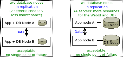
Bravura Security recommends either two or three database nodes, at different locations.
In this scenario each database node replicates to all other nodes
This does not mean linear replication. All application nodes are required to be DNS-resolvable and network-reachable from all other application nodes. All database replication ports (by default 5555 for data replication) to all application nodes must be reachable, not blocked by firewalls or other network appliances or rules. The file replication port (by default 2380) has to be reachable from the primary application node to all other application nodes. The file replication port must also be reachable from all other application nodes to the primary node.
See all Port requirements.
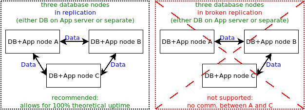
In this scenario, two database nodes replicate to each other. This cannot provide even theoretically 100% uptime, because attempting to resynchronize the two databases when they fall out of sync will take both nodes down.
In this scenario, there is one database node, with the database running on the same server as the application node, or on a separate server.
Though possible for demonstration and development purposes, Bravura Security does not recommend using a single database node for production purposes, as it becomes a single point of failure.
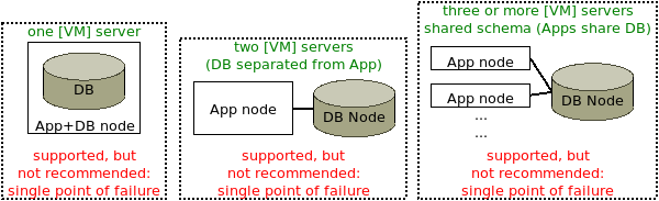
Shared schema environment
Replication can be configured with multiple application nodes using the same backend database. This is not recommended for a production instance with a single database node, because that would not be fault tolerant. See Fault tolerance: geographic distribution .
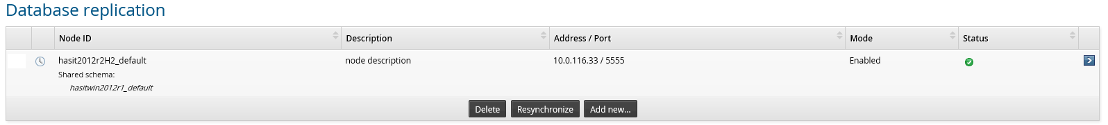
When an application node is added to an existing database node, all nodes that share the schema will be listed on the page; for example:
A Bravura Security Fabric instance, MYPASS, is installed on two different servers: A and B.
MYPASS (A) and MYPASS (B) are sharing the same data schema; that is, they store their data on the same database, or same database-native replicated database or cluster.
If either MYPASS (A) or MYPASS (B) is added as a replication node, both will be listed in the same database node row in the page, as illustrated below.
In database migration cases, when product administrators expect to find the node normally in direct replication, but forget to change the value from the schemaID table in the backend database, the product sees the node(s) with the same schemaID in shared schema instead.
In a shared-schema environment, re-synchronization must be disabled when you add a node to replication. On the Database Replication page, the option to Propagate and reload replication configuration on all servers (without resynchronizing nodes) is available for this purpose.
To learn how to install a node in a shared-schema environment, see Installing with a shared schema.
Combining database-native with application-level replication
The third available node topology is a hybrid (combination) of the direct application-level replication, and shared schema topologies introduced above. Each application node from a shared schema database node has to replicate with exactly one application node from all other database nodes; for example, in a hybrid replication topology with three application nodes providing web-based interface resources to each database node:
DB/Schema A | Replication | DB/Schema B |
Node A1 | <– –> | Node B1 |
Node A2 | <– –> | Node B2 |
Node A3 | <– –> | Node B3 |
Crucially, it is impossible to eliminate one application node and configure another application to replicate to two other application nodes serving the other database. For example, it is impossible to eliminate node A3 and then configure node A2 to replicate with both nodes B2 and B3; doing so would violate the constraint that node A2 must replicate into schema B exactly once. If node A3 is removed and not replaced, node B3 must also be removed.
The most complex configuration for replication is one where a database cluster with shared schema is combined with multiple application nodes. This is illustrated below in an example of a hybrid topology configuration using two shared schema database clusters.
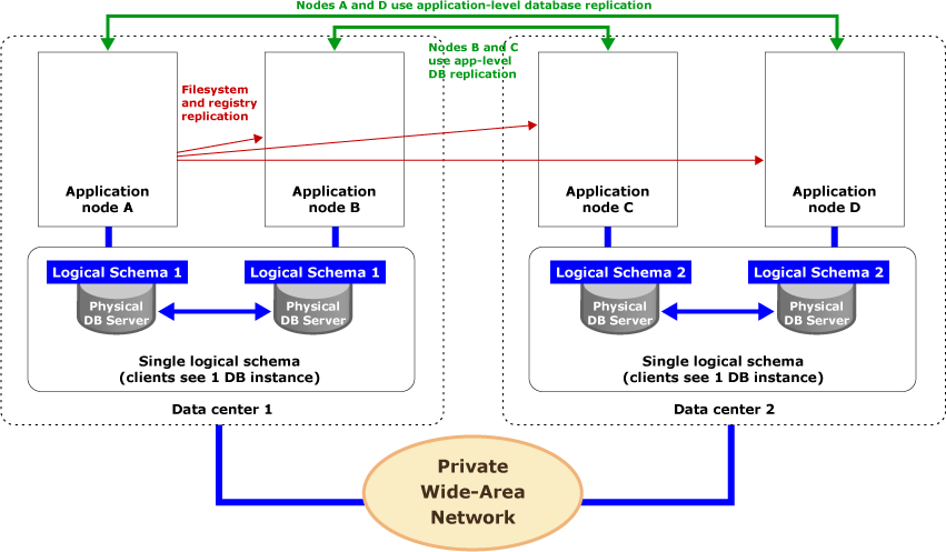
In this scenario, database-native replication creates fault-tolerant database clusters at each site. Each cluster appears as a single, local database instance to every application node in the same data center. Application-level replication involves replicating changes between corresponding application nodes at different sites.
Operationally, when application node A processes an update using stored procedure P1 in data center 1, native database replication between the two physical database servers in the cluster at data center 1 forwards the call to this stored procedure from one database server to another. In other words, application node B will see the results of P1, regardless of which physical database it calls, as a consequence of database-native replication. At the same time, P1 is forwarded from application node A to application node D at another data center, to be written into the database cluster there. Both application nodes will see the update results at the second data center because of physically local native replication in that database cluster.
File system and registry replication takes place independently of all this. In the above figure, application node A is the primary node. It pushes changes to its files/registry to all other application nodes and application proxies as a part of its nightly processing.
For more on file/registry replication, see File Synchronization .